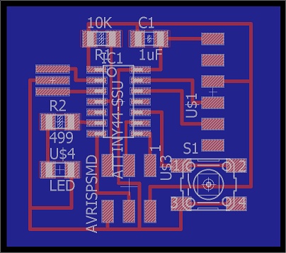
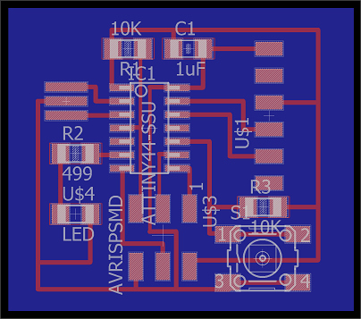
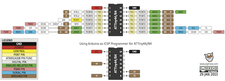
This week we were supposed to program the board that we designed in Week 5 to do something, with as many different programming languages and programming environments as possible. All three boards I made during that week were similar except for the one which had the LED and the button in series. This board would be hard to program as the LED is not in a complete circuit with the microcontroller. I have used the other two boards for this week's assignment. For both of those boards the button is on pin PA3 and the LED is on PA7 as shown in the board view:
I have found this color-coded diagram from this link very helpful when I needed to refer to the pin number of the ATTINY44.
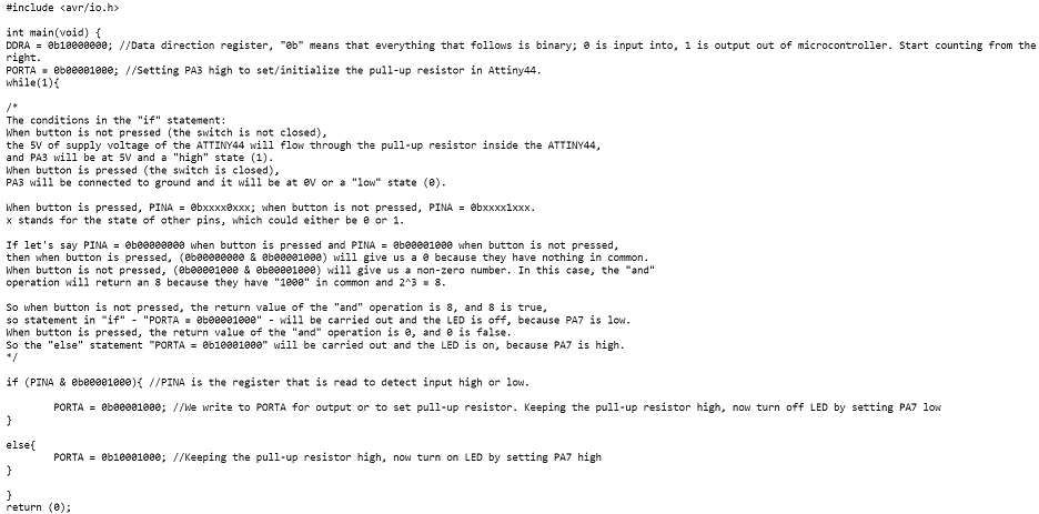
Rob has a great tutorial with three simple examples to light up an LED. Rob also helped me modify the code in TextMate to program my board and explained to me what the code meant. Here are the .make and .c files we created, as well as a screenshot of the c code in "Ye_001.c"; I also tried to write down how statements in the while loop work:
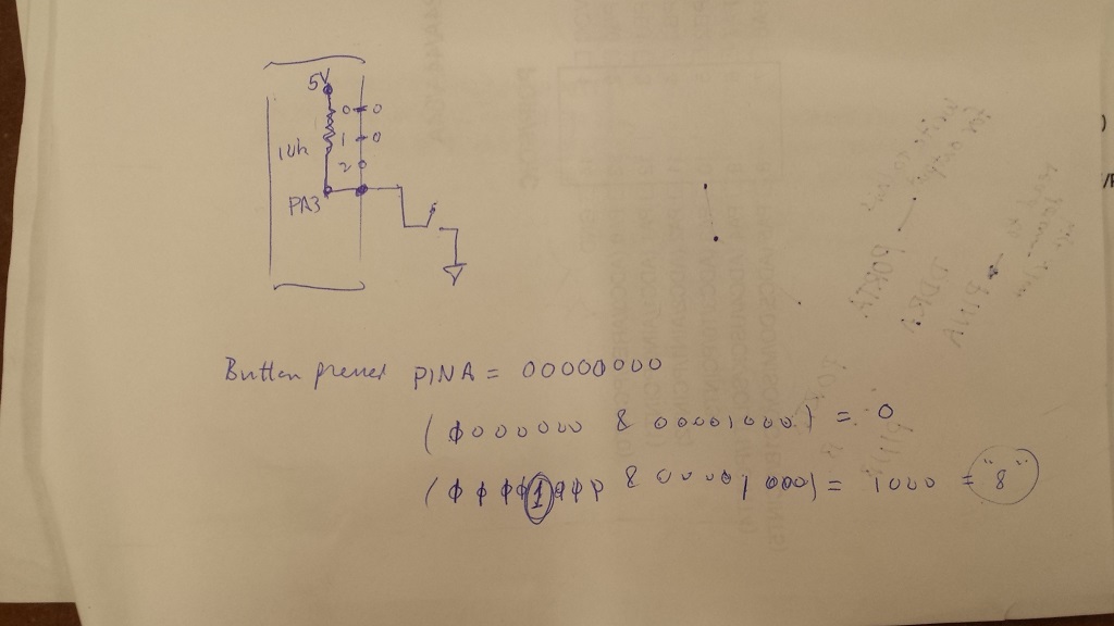
Here is the diagram that Rob drew to help me understand the if/else statments:
Once the files were ready, we used the following commends to program the board in the Terminal:
The result was that when the button was pressed, the LED would light up:
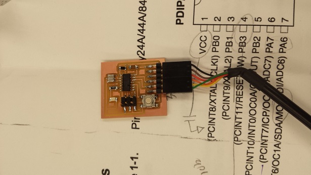
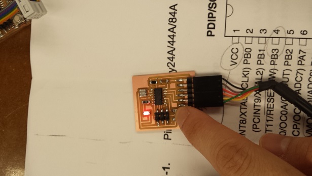
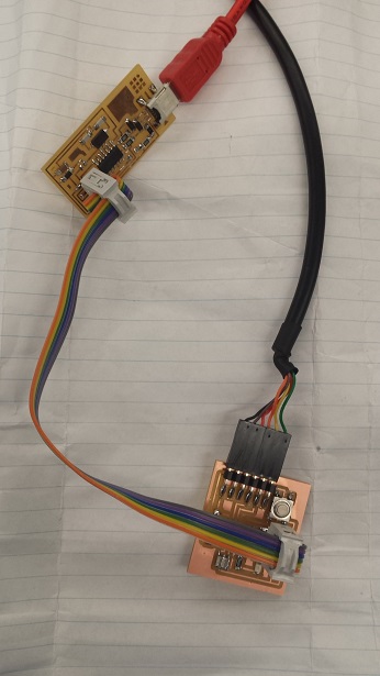
As I was trying to program my board I realized that my FabISP board from Week 2 did not work properly. Even though it was recognized as a FabISP USB on the Mac, my board could not be programmed successfully. At one point the 3x2 header connected the two boards incorrectly and we even saw smoke coming out of the FabISP board. This is a picture of how the 3x2 headers should connect to the boards:
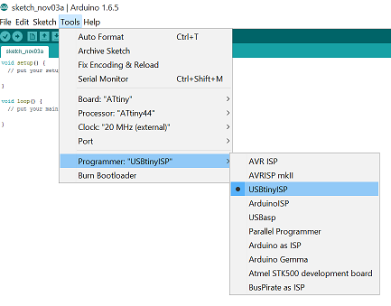
I also realized that my IDC ISP Cable from Week 2 didn't work either. (How did everything break at the same time!) So I borrowed Daphne's cable and Albert's FabISP board. Dan helped me figure out how to use Arduino to program the board in my Windows PC. After plugging in the FabISP board, we went to the Device Manager under the Control Panel. Then we installed the USBtinyISP driver downloaded from this site. (If this link becomes obsolete, try Googling "adafruit fabisp driver windows") We also followed this tutorial to install ATTINY support so that Arduino could recognize the ATTINY44.
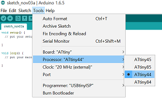
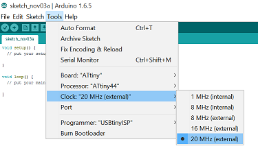
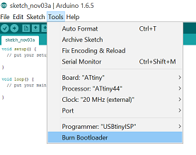
Before we could use Arduino to program the board, we had to make sure that the settings were correct, then we select "Burn Bootloader":
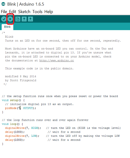
Once Arduino was up and running, I tried to use the some of the example codes under File...Examples...01 Basics. I tried the "Blink" and the "Fade" examples by changing the pin number of the LED in the code to reflect the pin number of the LED on my board. Here's a screenshot of the codes for blinking the LED and the video of the LED. (This video may only play properly on Safari, Chrome, and iPad/iPhone.) To program the board we would need to press the right-arrow icon on top.
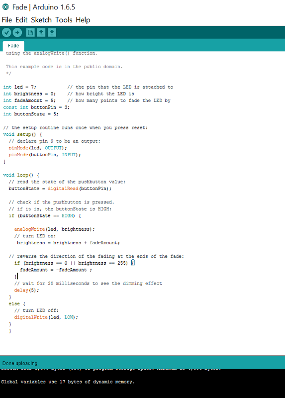
I also tried to combine the "Fade" example with the "Button" example, which was found under Files...Examples...02 Digital. I wanted the LED to keep fading and lighting up gradually until I press the button, at which point the light would turn off. The Arduino file is as attached.
In addition to the data sheet for ATTINY44, I found this link which provides a good explanation of the 3 registers - DDRx, PORTx and PINx. Rob also recommended the book Make: AVR Programming: Learning to Write Software for Hardware by Elliot Williams.
I will definitely try to troubleshoot my FabISP board and the IDC ISP cable. I also wanted to try the "echo hello-world" program later.
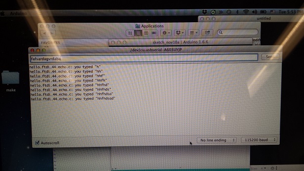
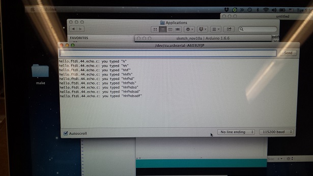
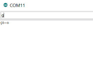
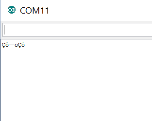
I tried the "echo hello-world" program during the output devices week. The board programmed okay from my Windows PC, but initially I was not able to get the serial monitor to generate the characters I typed:
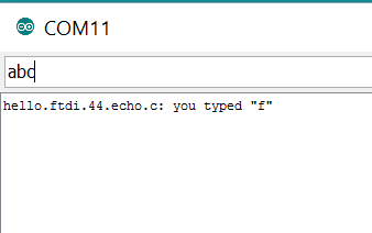
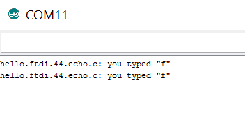
Dan mentioned that the baud rate might be wrong. When I switched from 9600 baud to 115200 baud, I was able to receive proper words and characters. But I still had a problem: the serial port always echos back the same letter no matter what character(s) and how many characters I typed in.
I tried to use Arduino on a Mac and got a different type of problem; the serial port was not echoing back the characters I put in and it added one more character to the previous string regardless of how many and what characters I typed in. We were not able to figure out why this happened.